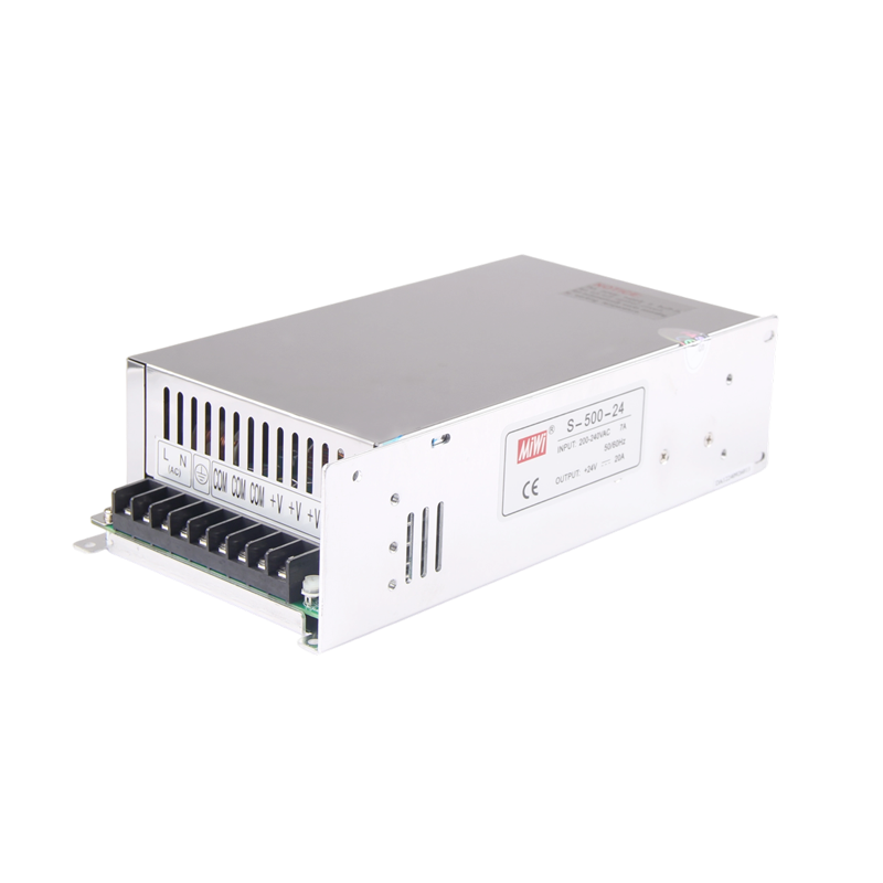
| Model Specification | S-500-12 | S-500-15 | S-500-24 | S-500-48 |
| OUTPUT | DC output voltage | 12V | 15V | 24V | 48V |
| Output voltage tolerance | ±1% | ±1% | ±1% | ±1% |
| Rated output current | 41.5A | 33A | 20.8A | 10.5A |
| Output current range | 0~41.5A | 0-33A | 0-20.8A | 0-10.5A |
| Ripple & noise | 200mVp-p | 200mVp-p | 240mVp-p | 240mVp-p |
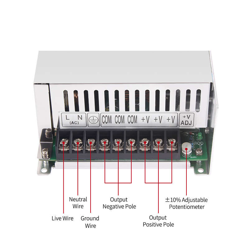
| DC adjustable voltage range | 10-13.2V | 13.5-18V | 20-26.4V | 41-56V |
| DC output power | 500W | 495W | 500W | 504W |
| Inlet stability | ±0.5% | ±0.5% | ±0.5% | ±0.5% |
| Load stability | ±1% | ±0.5% | ±0.5% | ±0.5% |
| Setup rise hold up time | 200ms,50ms,20ms |
| INPUT | AC input voltage range | 90~132VAC/180~264VAC selected by switch, 248~370VDC |
| Frequency range | 47~63Hz; |
| Input current | 6.5A/115V 4A/230V |
| AC impulse current | 25A/115V 50A/230V |
| Leakage current | <3.5mA/240VAC |
| Efficiency | 78% | 81% | 83% | 84% |
| PROTECTION | Overload protection | 105%~135%. Type,PULSING HICCUP SHUTDOWN; Reset,auto recovery |
| Over-voltage protection | 13.8-16.2V | 18-21V | 27.6-32V | 57.6-67.2V |
| High-temperature protection | RTH3>=65°C FAN ON<=55°C FAN OFF>=80°CCut off output(5~15V) |
| RTH3>=70°C FAN ON<=60°C FAN OFF>=85°CCut off output(24~48V) |
| ENVIRONMENT | Temperature coefficient | ±0.03%°C(0~50°C) |
| Vibration | 10~500Hz,2G 10min./1cycle,Period for 60min,EACH AXES |
| Isolation resistance | Input & output interval,Input & enclosure,Output & enclosure,500VAC/100M Ohms |
| Working temp & humidity | -10°C~+50°C,20~90%RH |
| Store tempe & humidity | -20°C~+85°C,10~95%RH |
| SAFETY & EMC Note 8 | Withstand voltage | Input & output interval,1.5KVAC.Input & enclosure,1.5KVAC. Output & enclosure,0.5KVAC |
| Safety standards | Design refer to UL1012, EN60950-1,EN61347-1,EN-61347-2 approved |
| EMC standards | EN55015,EN55022,EN55024,EN61000-2,EN61000-3,EN61547 approved |
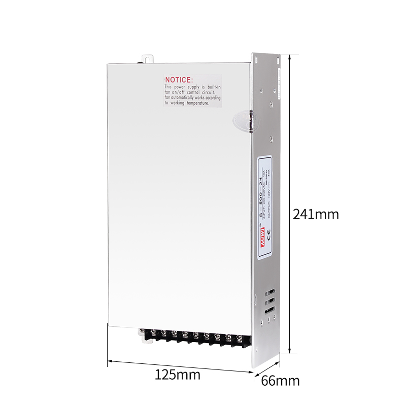
| OTHERS | Overall dimension | (L×W×H) 241*124*65 mm |
| Weight | 1.4Kgs /10pcs per carton |
| NOTE | 1.The testing condition for the parameter above is,230VAC input, rated load,25°C 70%Rh,Humidity |
| 2.Error,include the setting error, line stability and load stability.(Note,5) |
| 3.Wave test,adopting“A12”double wire for 20MHz,and 0.1uF&uF capacitor short-circuit for interrupting |
| 4.Inlet voltage stability test, when is over load, the lowest voltage of inlet is representative to the highest voltage. |
| 5.Load stability test: The load is from 0% to 100%,others 60%. |
| 6.C2,3,11must be knocked down |