| Model Specification | T-60 A | T-60 B | T-60 C |
| DC Output Voltage | 5V | 12V | `-5V | `5V | 12V | `-12V | 5V | 15V | `-15V |
| Iutput Voltage Error | ± 2% | ± 5% | ± 5% | ± 2% | ± 6% | ± 6% | ± 2% | ± 6% | ± 6% |
| Rated Output Current | 7A | 3.5A | 1A | 7A | 3.5A | 1A | 7A | 3A | 1A |
| Output Current Range | 0.6-7A | 0.2-1A | 0.2-1A | 0.6-5A | 0.2-1A | 0.2-1A | 0.6-4A | 0.2-1A | 0.2-1A |
| Tripple and Noise | 100mVp-p | 100mVp-p | 100mVp-p | 100mVp-p | 100mVp-p | 100mVp-p | 100mVp-p | 100mVp-p | 100mVp-p |
| Iniet Stability | ± 0.5% | ± 1% | ± 0.5% | ± 0.5% | ± 1% | ± 0.5% | ± 0.5% | ± 1% | ± 0.5% |
| Tolerance Voltage | ± 1% | ± 4% | ± 1% | ± 1% | ± 4% | ± 1% | ± 1% | ± 4% | ± 1% |
| DC Output Power | 57.5W | 61W | 62.5W |
| Efficiency | 72% | 72% | 72% |
| Adjustable Range for DC Voltage | `+10, -5% | ± 10, -5% | ± 10, -5% |
| AC Input Voltage Range | 85~132VAC/170~264VAC selected by switch 47~63Hz; 240~370VDC |
| Input Current | 2A/115V 1A/230V |
| AC Inrush Current | Cold-Start Current: 30A/115V, 60A/230V |
| Leakage Current | <1mA/240VAC |
| Overload Protection | 105%~150% Type: Foldback Current Limiting, Reset: Auto Recovery |
| Over Voltage Protection | ………… |
| High Temperature Protection | ………… |
| Temperature Coefficient | ± 0.03% /℃ (0~50℃) |
| Start, Rise, Hold time | 800ms,50ms,16ms/ 115VAC; 300ms,50ms,80ms /230VAC |
| Vibration | 10~500Hz, 2G 10min,/1cycle, a total of 60 minutes, Each axes |
| Withstand Voltage | Between Input and Output: 1.5KVAC, Input and Shell: 1.5KVAC, Output and Shell: 0.5KVAC |
| Isolation Resistance | Input and Output Intermal: Input and Enclosute, Output and Enclosure: 500VDC/100M Ohms |
| Working Temperature and Humidity | `-10℃~+60℃ (Refer to Output Derating Cutve), 20%~90%RH |
| Storage Temperature and Humidity | `20℃~+85℃, 10%~95%RH |
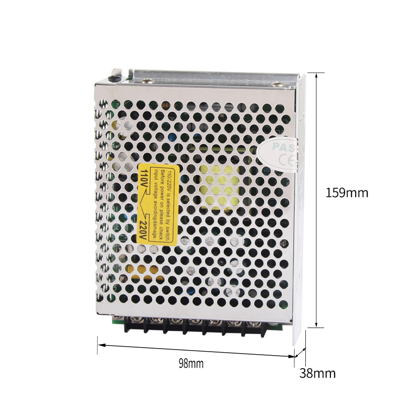
| Overall Dimension | 159*98*38 mm |
| Weight | 0.56 kgs |
| Safety Standards | CE |
| EMC Standards | Meet FCC Part 15J Conduction class B |
| 1. The testing condition for the parameter above is: 230VAC input, rated load, 25℃ 70%Rh, Humidity. |
| 2. Error, include the setting error, line stability and load stability. |
| 3. Wave test: adopting "A12" double wire for 20MHZ, and 0.1uF&uF capacitor short-circuit for interrupting. |
| 4. Inlet Voltage Stability test: when is over load, the lowest voltage of inler is representative to the highest voltage. |
| 5. Load stability test: the load is from 0% to 100%, others 60%. |
| 6. Total output canbe maximum Current, total load can not exceed the maximum output power. |
| 7. C2,3 must be knocked down. |