

| Model | DR-120-12 | DR-120-24 | DR-120-48 | |
| OUTPUT | DC Voltage | 12V | 24V | 48V |
| Rated Current | 10A | 5A | 2.5A | |
| Current Range | 0-10A | 0-10A | 0-2.5A | |
| Rated Power | 120W | 120W | 120W | |
| Ripple & Noise (max.) Note.2 | 80mVp-p | 80mVp-p | 100mVp-p | |
| Voltage Adj. Range | 12-14V | 24-28V | 48-53V | |
| Voltage Tolerance Note.3 | ±2% | ±1% | ±1% | |
| LINE REGULATION | ±0.5% | ±0.5% | ±0.5% | |
| LOAD REGULATION | ±1% | ±1% | ±1% | |
| Setup, Rise Time | 500ms,70ms/230VAC 500ms,70ms/115VAC at full load | |||
| Hold Up Time | 36ms/230VAC 32ms/115VAC at full load | |||
| INPUT | Voltage Range | 88~132VAC/176~264VAC selected by switch 248~370VDC | ||
| FREQUENCY RANGE | 47~63Hz | |||
| AC Current | 2.6A/115V 1.6A/230V | |||
| Efficiency | 80% | 84% | 85% | |
| Inrush Current | COLD START 20A/115VAC 40A/230VAC | |||
| LEAKAGE CURRENT | <3.5mA / 240VAC | |||
| PROTECTION | Over Load | 105%~150% rated output power | ||
| Protection type: Constant current limiting, recovers automatically after fault condition is removed | ||||
| Over Voltage | 15 ~ 16.5V | 29 ~ 33V | 58 ~ 65V | |
| Protection type : Shut down o/p voltage, re-power on to recover | ||||
| OVER TEMPERATURE | 85°C±5°C(TSW1) | 90°C±5°C(TSW1) | 90°C±5°C(TSW1) | |
| Protection type : Shut down o/p voltage, recovers automatically after temperature goes down | ||||
| ENVIRONMENT | Working Temp., | -10°C~+60°C; (Refer to "Derating Curve") | ||
| WORKING HUMIDITY | 20 ~ 90% RH non-condensing | |||
| Storage Temp., Humidity | -20°C~+85°C; 10%~95%RH | |||
| Temp. Coefficient | ±0.03%/°C(0~50°C) | |||
| Vibration | 10~500Hz, 2G 10min./1cycle, period for 60min, each along X, Y, Z axes | |||
| SAFETY | Withstand Voltage | I/P-O/P:3KVAC I/P-FG:1.5KVAC O/P-FG:0.5KVAC | ||
| Isolation Resistance | I/P-O/P, I/P-FG, O/P-FG:100M Ohms / 500VDC / 25°C / 70% RH | |||
| OTHERS | MTBF | 432.1K hrs min. MIL-HDBK-217F (25°C ) | ||
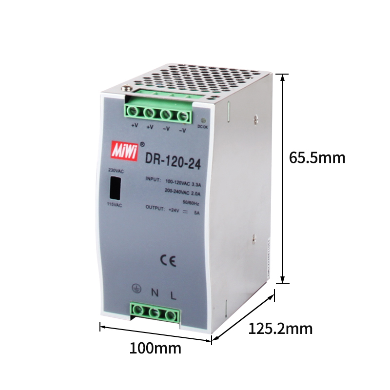
| DIMENSION | 65.5*125.2*100mm (W*H*D) | |||
| NOTE | 1. All parameters NOT specially mentioned are measured at 230VAC input, rated load and 25 of ambient temperature. 2. Ripple & noise are measured at 20MHz of bandwidth by using a 12" twisted pair-wire terminated with a 0.1uf & 47uf parallel capacitor. 3. Tolerance : includes set up tolerance, line regulation and load regulation. 4. The power supply is considered a component which will be installed into a final equipment. The final equipment must be re-confirmed that it still meets EMC directives. | |||
